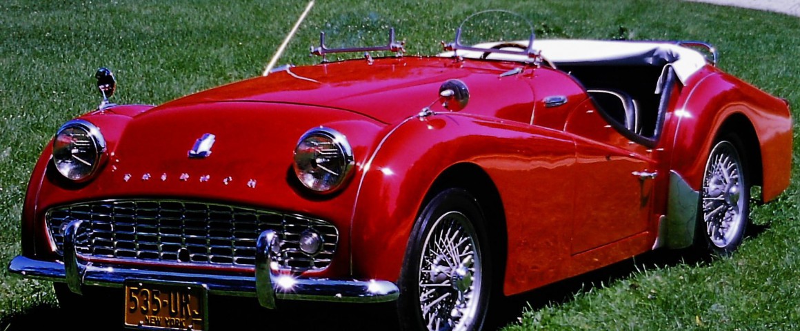
TR3A Upgraded With Automation Controls and a Color Touch Screen
By Joe Gaglio
In 1966 when I purchased my first car – a 1954 Triumph TR2, I began to understand and experience the enjoyment and failings of the British sports cars. Two years later, I sold it and went to college. However in 1974, I obtained a 1959 TR3A, this time with the intention of restoring it.

The project finally got under way in the early 2000s. Instead of using the original gauges and switches, I opted to replace them with a Factory Automation control system comprising a Programmable Logic Controller (PLC) and color touch screen. Mine was not to be a show car, but one that was fun to have and drive. This choice provided a more reliable electrical system with the features of the touch screen and built-in security!

A key is not used to start the car, so a security system was needed to prevent anyone from driving it. Using the touch screen a simple and secure scheme was implemented. Upon power-up, the STARTUP screen appears. Touching the hidden-cell advances you to the second screen which is identical to the first screen. The transition from one to another identical screen is without flicker or any visual indication. When the hidden cell is pressed, the PASSWORD screen appears. Once the proper password is entered, a “GOTO SCREEN” button is displayed which allows you to select the MAIN screen and operate the car.

Startup Screen
The control switches – Ignition, Starter, Wipers, Lights and Hi Beam are part of the MAIN screen. Run time operational conditions – Water Temperature, Oil Pressure, Battery Voltage and Fuel Level are monitored by sensors and transmitters/transducers. Several Run screen variations have been included such as dials and a night screen.

Main Screen

Run Screen

Dials

Night
The actual fuel level is calculated, not measured. When refueling, the amount of fuel added is entered on the FUEL screen and then the FUEL ADDED button is pressed. The driver also enters the expected speed to be driven. The PLC calculates the fuel usage based on 20 MPG at 45 MPH. Three usage factors (one per setting for 30, 45 and 60 MPH) enable adjustment of the fuel usage.

Fuel Screen
The original system utilizes a 12 VDC positive ground. Overcoming the positive ground was required as the control system needed 24 VDC and a negative ground or common. This issue was solved using the following devices and practices:
- A DC-to-DC power supply (12V to 24V) with a floating common negative.
- An ungrounded thermocouple with an isolated (input/output) transmitter.
- An isolated Voltage transmitter was used to measure the battery voltage. All transmitters outputs are 4/20 mA.
- 5 – Ten Amp “ice cube” relays isolate the PLC relay outputs to the ignition, lights, high beams, starter and wipers.
Note: The control system logic and wiring are available by request at no charge via email.
Joe Gaglio
Email: joegagliotr3@gmail.com
Phone: 508-274-7313


'A Dash of Modern Touch!' has 1 comment
August 22, 2019 @ 9:10 am Rod Hamilton
This is very clever, I really like the touch screen.
Rod