


Most people first learn about generators at night on a back country road in the middle of nowhere. (Actually, about 100 yards from a house, but the middle of nowhere is so much more depressing.) You have one of those “English sports car needs minor electrical work” from the classified ads. Oh, the man who sold you the car was honest; the car was most certainly English and it did need electrical work. Anyway, after standing over the open engine compartment and alternately thumping on the generator, the control box, and the flashlight, you conclude that although flashlights improve with thumping, generators and control boxes don’t.
Perhaps the best way to come to grips with old electrics is by gaining an understanding of what makes them work. Contrary to popular belief, the operation of a Lucas generator is not based on some magic incantation – it is based upon five fundamental properties of electricity and magnetism:
1) Electric current in a coiled wire will create a magnetic field.
2) Wrapping the coil of wire around a soft iron core will intensify the magnetic field.
3) The strength of the magnetic field will vary with the current in the wire.
4) Rotating a loop of wire in a magnetic field will induce a voltage in that loop of wire.
5) The strength of the induced voltage is dependent upon the strength of the magnetic field and the speed at which the loop of wire is rotated.
Generator Basics
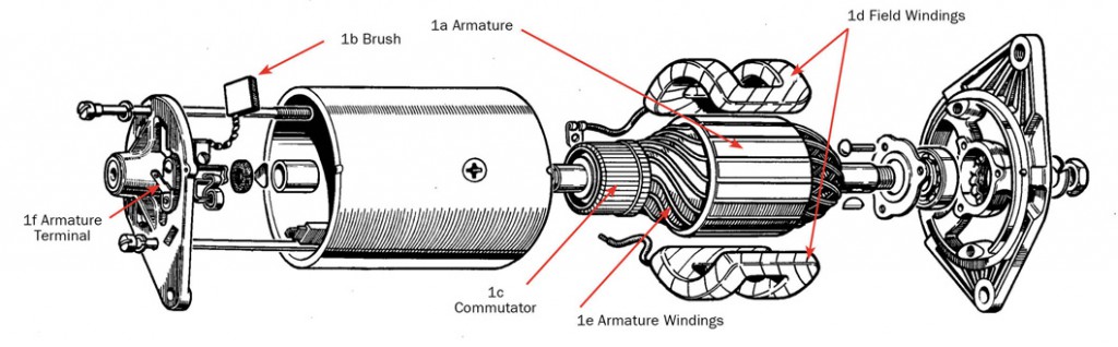
A generator, like that low rpm generator, is composed of five parts. The armature (1a) is made up of coils of wire wrapped around an iron core, and it is the armature which rotates when the generator pulley is turned. The brushes (1b) are the spring-loaded contacts which transfer current from the armature to the electrical system. The brushes actually rest against a segmented ring at one end of the armature called the commutator (1c). Inside the generator body are the field coils or field windings (1d). These consist of fine copper wire wrapped around the field poles, which are essentially pieces of soft iron. It is current in the field coils or windings that produces the magnetic field in which the armature rotates.

The electrical system operates on the properties of various metals and the principles of magnetism. It is the most scientifically advanced system in your car, but this step-by-step guide lays it all out.
When the engine is turning over, the armature (1a) is spun by the fan belt. In the presence of a magnetic field generated by the field windings (1d), a voltage is induced (created) in the armature windings (1e). When the voltage in the armature windings (1e) is greater than the rest of the system, current will flow from the armature windings (1e) through the commutator (1c), through the brushes (1b), finally arriving at the armature terminal (1f) of the generator (usually marked “D”). The current then flows through the wire running to the “D” terminal of the control box or voltage regulator.
Control Box
The control box (or voltage regulator as most of us call it) has two main parts. The cut-out relay (2e) prevents current from flowing to the generator from the battery when the generator’s output voltage is lower than battery voltage. The second part of the control box is properly called the voltage regulator (2k). This strengthens or weakens the magnetic field in the generator according to the needs of the battery or other electrical system components. Remember, the stronger the magnetic field, the greater the voltage induced in the spinning armature. The cut-out relay (2e) consists of an iron core with two layers of wires wound around the core. The inner wrapping of wire is called the “shunt windings” and the outer wrapping is called the “series windings”. The shunt windings, which are hidden under the series windings, are connected between the armature terminal “D” on the generator and a ground terminal (usually marked “E”) on the control box.
This means that the internal generator voltage is always impressed upon the shunt windings. All the generator output current passes through the series windings (2g, 3g) before going to the electrical system in general.
Fixed above the cut-out core is a spring arm that carries a contact (2i, 3i) which is connected to the series windings (2g,3g) of the cut-out core. Output current from the generator can only pass on to the electrical system and the battery when the cut-out contact arms (2i,3i) are touching. Spring tension normally holds the contacts apart so there can be no current flow in either direction.
Cut-Out Relay at High/Low RPMs
When the armature in the generator is spinning fast enough, (about 1000 generator RPM or 750 engine RPM) the current in the shunt windings (3f) of the cut-out relay will generate a magnetic field strong enough to overcome the natural spring tension of the contact arm (3i) and it snaps down bringing the two contacts together. Current now flows through the series windings (3g), across the contacts and out the arm (3i), finally reaching the output terminal (usually “A”) on the control box. From there, it goes on to the ammeter (if fitted) and then to the battery. This current now flowing through the series windings (3g) actually intensifies the magnetic field around the core (3h) of the cut-out relay, and this in turn holds the arm down even more firmly, pressing the contacts (3i) together. The point when the contacts close is usually adjusted so that the internal voltage of the regulator is about 12.7 to 13 volts.
When the engine slows to idle, the armature slows down as well. This means that the voltage induced in the spinning armature (3a) drops. Lower voltage reduces the strength of the magnetic field holding the series winding’s contacts (3i) closed. Eventually, the weakened magnetic field can no longer hold against the arm’s spring tension and the contacts open. (Note: the way in which the contacts open is actually somewhat more complex, but this description will do for our purposes.) This immediately stops all current flow to or from the generator. The point at which the contacts open (around 8.5 to 11 volts) is known as the drop-off point. If the series winding contacts in the cut-out relay did not open at low generator output, the higher battery voltage would flow back through the control box, through the wiring harness and into the armature’s fine wire windings in the generator. The reverse current flow would melt the windings and thus destroy the generator. Now you know one of the reasons why the control box is so important.
Voltage Regulator
The other half of the control box, the voltage regulator (2k, 3k), acts to limit the voltage in the charging system to a safe value by controlling the internal voltage of the generator. The voltage regulator, like the cut-out, has a shunt winding (3m) made up of many turns of fine wire wrapped around a soft iron core. Suspended above the regulator core are a pair of contact points (3n), similar to the cut-out relay. However, these points are normally closed, rather than open. When the points are closed, the output current from the “D” terminal on the generator goes through the regulator frame (3l), through the regulator contacts (3n) to the field terminal on the control box (usually “F”). From this field terminal, the current flows to the field terminal (“F”) on the generator and then through the field windings (3d) around the field poles of the generator. The current in the field windings (3d) creates the magnetic field around the armature (3a). The armature spinning inside this magnetic field generates the electric current that feeds the battery and the rest of the electrical system. The function of the regulator is to break this connection.
When the generator is spinning slowly, generator output voltage is low. This means the current in the regulator shunt windings (3m) is weak, and the magnetic field created by this weak current is unable to overcome the spring tension in the arm holding the regulator contact points (3n) closed. As we spin the generator faster, the output voltage increases. As a result, we see increased current flowing into the voltage regulator through the “D” terminal. This increased current continues, flowing through the regulator shunt windings (3m), through the regulator contacts (3n), out through the “F” terminal on the voltage regulator and back through the field windings (3d) in the generator. Since we have a direct connection through the regulator contacts (3n), current in the field windings (3d) increases as the generator spins faster. Consequently, the magnetic field (in which the armature spins) created by the increased current in the field windings (3d) is also increasing. Because the magnetic field is stronger, the induced voltage in the armature is also increasing. As the output voltage from the generator continues to increase, the current in the shunt windings (3m) of the regulator relay also increases, which increases the strength of the magnetic field trying to pull the regulator contacts (3n) apart.
When the generator output is high enough, the strength of the magnetic field generated by the current in the regulator shunt windings (3m) finally overcomes the natural tension of the contact arm and the regulator contacts (3n) are separated. The direct connection between the armature terminal “F” of the generator and the field terminal “F” of the control box is broken. Although the direct connection has been severed, there is still a way for the current from the generator to return to the field windings.
Backdoor Current
This second path is through a short piece of resistance wire (3p) connecting the regulator frame (3l) to the “F” terminal on the voltage regulator. Output current from the generator can still get to the field windings in the generator, but the built-in resistance of the wire reduces the current passing through the field windings (3d) which reduces the strength of the magnetic field in which the armature is spinning. The voltage induced by the magnetic field in the armature windings falls, and so generator output falls as well. With reduced generator output, the current in the shunt windings (3m) of the regulator is also reduced, and the magnetic field produced by the current in the shunt windings is likewise reduced. When the strength of the magnetic field is no longer enough to hold the regulator contacts (3n) apart against the spring tension in the arm, they snap back together, and direct contact between the generator output and the field windings is restored.
Since current is no longer flowing through the resistance wire, the current in the field windings (3d) of the generator is increased, which strengthens the magnetic field inside the generator. The induced voltage in the armature increases, and the generator output also increases. As generator output increases, current in the shunt windings (3m) of the regulator increases once again until the magnetic field is strong enough to pull the regulator contacts (3n) apart. As before, with the direct connection broken, the current to the field windings is reduced by the passage of current through the resistance wire (3p). The strength of the magnetic field in the generator falls, and so the generator output falls. The cycle described here takes place very quickly; so quickly that the contact points seem to vibrate.
We’ve now traced the system through its entirety. With this knowledge in hand, you’ll be able to entertain your companions with a profound dissertation on the fundamental properties of electricity and magnetism which make thumping on the generator and control box useless. We all know that once the magnetism has leaked out, there is nothing anyone can do.
By Michael Grant, Moss Technical Services

'Generators & Regulators – A Magnetizing Primer' have 3 comments
July 21, 2018 @ 5:43 am Chris
Very well explained. I had to fault find a 750kw generator and so had to go back to first principles.
Your narrative helped .
October 15, 2022 @ 11:36 am Paul Wanamaker
When the car first starts, is there a short period of the regulator stabilizing before it settles on the regulated voltage
Also, will that charging voltage measured at the battery slightly decrease as the engine compartment warms up
In my case when I first start the car the voltage at the battery goes to about 14.5 to 15, then settles to around 13.7. Over a period of time as I’m driving, the charging voltage at the battery will drop to around 13.2
Is this normal?
Thank you for your help, Paul Wanamaker
August 4, 2023 @ 6:24 am Mike G
Regualtor controlled voltage should/will be higher at cold temperatures and reduce in warmer weather such as that under the Bonnet. This reading is normally done with a temperature thermostat mounted on the regulator (control box housing), engine compartment closed, radiator cooling fan acting on the control box under all operating environments. This type of stat is a special tool used for this purpose. This is the theory anyway. The short answer is yes this is normal.