


Dragons live forever, but not so little boys, or should that be: distributors live forever but not so generators? Your pre-1968 LBC almost certainly has a Lucas generator, and it has probably been through the ringer…two or three times! This is another fairly simple device that can be nursed along almost indefinitely, so get hold of yourself and resist that overpowering temptation to replace it with an alternator.
The secret to a long generator life is regular maintenance. The brushes, bearing and bushing should be inspected and lubricated annually, which will require some disassembly. That little “oil here” orifice is not going to cut it. The brushes are a snap to change, but the bearing is more difficult and the bushing nearly impossible…well at least for the typical shade tree mechanic.
 If you are having trouble already, here are some simple tests. If the battery is not charging, disconnect the wires from the generator, and then measure the resistance from the small terminal to ground, which should be about six ohms. If that’s okay, measure between the two terminals, which should be about seven ohms. If that’s okay, connect the two terminals together with a short piece of wire. With the engine running at 1200 RPM, measure the voltage from either of the joined terminals to ground. A reading of about 20 volts, depending on engine speed, indicates the generator is working properly. Some common problems are worn brushes, broken brush springs, loose ground rivet, shorted coils and worn bearings or bushings. A generator with a shorted field coil will almost always take the voltage regulator with it, requiring repairs to both units.
I have been disappointed with the work of local generator shops; they are few and far between and typically do only just enough to get the thing working. New generators are available for most of the four cylinder cars…cheap, too!
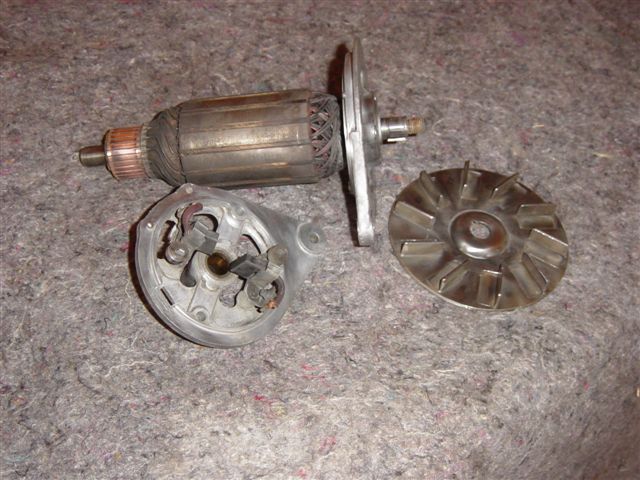
After all, this a DYI column, so lets take the damn thing apart! Start by removing the pulley nut with an impact wrench, then pop off the pulley. Well, actually if it doesn’t come off easily by hand, use a puller, as it is incredibly easy to chip a pulley. Don’t hammer on the end of the shaft either, as it made of something akin to silly putty. Pry the woodruff key out of the armature shaft (better have a new key handy). Next remove the two long skinny bolts that hold the front and back plate together. The rear plate should come off first. The front plate holds the bearing and will come out of the case with the armature attached. A usable bearing will go like crazy when you hold the plate in a vise and spin the armature like a top (if you played with a top…you’re old).
Even a brand new bearing will have some play…better to check it with the generator assembled. To replace, drill out the three rivets that hold the bearing retainer plate to the front plate. The bearing should fit snuggly in the front plate and on the armature. If the new bearing does not, Lock-tite products are available to hold them. Of course, there is always JB Weld! Note the position of the spacers on either side of the bearing. New bearings are sealed units and can actually be reassembled without the retainer, as long as the spacers are in place.
 The rear plate holds the brushes and the bushing. Inspect the brushes and the brush springs for wear, tear, and ease of movement. If you are in there already, you might as well replace the brushes, taking care to route the wires out of harms way on reassembly. Once in place, push each brush up in their holders and pull the spring back until the end of the coil spring catches the brush and holds it in position to clear the commutator on reassembly.
The bushing can, with a little luck, be removed with a tap. I don’t mean hit it…a tap is a tool for making threads. If it will not pull out, drill out the silly oil hole and drive the tap (along with the bushing) out with a small punch. I sometimes thread the now enlarged hole and screw in a grease fitting at this point. The new sintered bronze bushing should be soaked in oil overnight, and gently pressed into place with an appropriately sized bolt, as it is more fragile than it looks.
There is a paragraph or two in the manual about refurbishing the commutator, but shining it up with some fine Emory cloth will generally suffice. Check for loose segments and broken or skinned wires. There is so little resistance in the armature windings that it is impossible to detect a shorted coil, but you can check for shorts to the armature shaft. A fiber washer or two should be in place on the shaft at the commutator end. These can be used to control end play on reassembly.
The case has two field coils and the insulated terminal for them is riveted to the case with the rivet providing the ground connection. The coils are wrapped in cloth, which will appear to predate most Egyptian mummies. If you are really into this, the screws retaining the field coils can be removed with an impact screw driver bit (hand tool) inserted into an impact wrench (air tool). Nothing else will budge them. You can drill out the aforementioned rivet and remove the coils, which can be re-wrapped with friction tape. No, I’m not kidding!
 Hopefully, you have been cleaning, detailing and painting as you go. Put the front plate and armature assembly (you did put it back together, right?) in the vise (easy, now) and carefully set the newly refurbished case onto it so that the alignment notch in the bottom of the case sits on the little stud on the rim of the plate. If the stud has gone missing, replace it with a small screw. Check the wires between the field coils to make sure that they don’t touch anything. There should have been some thin cardboard insulators that would hold the wires away from the case and prevent the long bolts from touching the wires. You can fabricate some new ones or just use some ¼” heat shrink tubing to insulate the bolts. Lower the bolts and rear plate into place, carefully watching that nothing is getting pinched. With the plate fully in place, fish around with the bolts until you find the bolt holes in the front plate. Push the brushes into place with a small screw driver through the openings in the rear plate (most models), making sure the spring ends rest on top of the brushes. Now, tighten the bolts, and then turn the generator around, rear plate down in the vise. Place the woodruff key (lost it, didn’t you), the fan, pulley, lock washer and nut on the armature shaft. Tighten the nut and…you’re done, buddy!
The refurbished generator should turn easily with no end play and the new brushes will probably make a clicking noise until seated. Of course, it should pass the generator tests with flying colors, although I have noticed that occasionally a generator must spin for a few minutes before the brushes make good enough contact for reliable operation.
By Mike McPhail
Gulf Coast Austin-Healey Club
Hill Country Triumph Club


'Pint Size Project — The Generator' has 1 comment
September 5, 2016 @ 2:42 pm TD.
Two things:
First, there is no mention of removing the gear drive for the tach. I’m still messing with it, but it seems determined to stay attached. Now, moving on to the pulley. Cripes! I can’t get it to budge and don’t have an impact wrench. Suggestion? I’m afraid of putting it in a vice to hold it better. Ready to chuck this project and take it to a pro.