


Moss’s new kit juices up MGAs and early Bs
By the Moss development staff
Technological advancements allow today’s cars to be more reliable than ever. Although true purists demand period authenticity, people who want to spend more time driving their British sportscars and less time repairing them generally embrace advancements. Knowing this, Moss Motors’ latest performance system is an alternator conversion kit (130-078, 130-088) for 1955-62 MGAs and pre-1968 MGBs.
An alternator provides two prominent benefits over the OE generator: greater dependability and increased power output. The stock generator’s relay-type voltage regulator wasn’t the most reliable unit, and the Moss kit’s Lucas alternator produces a maximum of 36 amps of power compared to the OE generator’s 22 amps. So, the alternator is able to charge the battery while powering more DC accessories: stereo systems, radar detectors, and such. Plus, the alternator generates more juice at lower engine speeds and weighs less than the generator.
Preliminaries
The competent home mechanic should be able to complete the conversion with few worries. Ordinary hand tools are required, as are an impact wrench, wire cutters/crimpers, and a multimeter.
The process also involves converting the car from positive earth to negative ground. This entails swapping the battery cables (or turning around the connecting wire for cars that have dual 6-volt batteries). Polarity must also be changed on the fuel pump, voltmeter/ ammeter, electronic tach, electronic ignition module, and car radio where applicable.
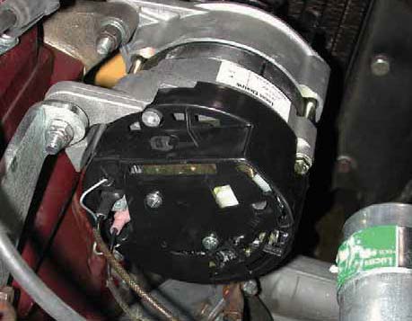
Highlights of the Moss Motors alternator conversion are shown here. For more in-depth information, please visit www.mossmotors.com.

The Moss kit includes a Lucas alternator, pulley, fan, belt, brackets wiring connectors, and instructions. The kit also adapts to Moss-supercharged MGBs.
1. Remove the coil from the generator. Position it on the right side of the firewall, marking and drilling two holes for the coil bracket.

2. Mount the coil, then reverse the wires since the polarity will now be negative ground.

3. If the MG has an electronic ignition, it must be swapped for a negative ground application. Also reverse the wires on an ammeter or voltmeter if the car has one.

4. If the car has an SU fuel pump with a positive ground diode, reverse the diode wires/connectors after removing the pump. Solid-state pump will have to be replaced with a new pump (377-225).


5. Loosen the generator’s mounting and adjustment bolts, rotate the generator, and remove its belt.

6. Reuse the hardware to attach the kit’s alternator bracket to the block.

7. Assemble the alternator with the kit’s fan and pulley.

8. Mount the alternator by sliding the slot in the adjuster over the threaded stud on the pillar. Then line up the alternator’s front ear with the water-pump bracket and secure using the original hardware. Make sure that the alternator is at full droop.

9. Wire the alternator, converting the original ring-type connectors to spades if necessary; heat-shrink tubing is included in the kit for weatherproof connections. The original yellow/green wire connects to the smaller terminal, and yellow wire can go to either of the larger terminals.

10. Install the new belt: wrap it around the water pump pulley and then walk it onto the alternator pulley. Put a towel over the alternator, then use a prybar between the alternator and block to tension the belt. Tighten the adjuster nut, allowing 3/16” to ¼” of belt deflection.

11. Unscrew the regulator and turn it over to access the terminal posts (screw-type shown).

12. Move the yellow wire from “D” to “A” and yellow/green from “F” to “D.” Use a multimeter to test continuity and the alternator leads for verification. Remount the regulator.

13. Spade-connector regulators require wire stripping and connection crimping. Disconnect the yellow wire at the “D” terminal, strip the insulation, and crimp on the kit’s male spade connector. At the “A” terminal, identify the wire that doesn’t go to the battery, crimp the kit’s yellow wire tap on it, and connect the spade connector to the tap. Relocate the yellow/green wire from “F” to “D” using the kit’s female spade connector and heat-shrink tubing.

14. Swap the battery cables, ensuring that the negative post now goes to ground. Turn the key to ON and look for smoke or sparks. If clear, start the car and test voltage with a multimeter. Voltage should be above 13 at idle, increasing at higher rpm.


'Alternator Upgrade' has no comments
Be the first to comment this post!