


While we are on the subject of Lucas electrics, let’s take a look at some of the components. A vital, but often neglected item is the distributor. This hard working gadget often performs faultlessly for decades, but may very well be in need of servicing.

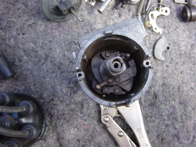
The innards which create centrifugal advance.
The distributor is a fairly simple mechanical device that has changed little over the years. It has several functions:
• Switching current on and off to the coil to generate a timed spark
• Directing the spark to the proper spark plug
• Advancing the timing as the engine revs
A cam on the distributor shaft, which is driven by the cam shaft, opens and closes the points when the engine is turning. When the cam lifts the contact points and breaks the ground circuit to the coil, a spark is generated. The spark wire from the coil is connected through the distributor cap to the rotor, sitting on top of the distributor shaft. The spark jumps from the rotor to the spark plug wire terminal of the cap and on to the spark plug.
As the engine speed increases, a pair of weights under the plate works against springs holding the top section of the shaft. This centrifugal action causes the rotor to rotate, which advances the timing. A timing light will verify this phenomenon: just rev the engine and observe the motion of the timing mark. It should move over thirty degrees at 3000 rpm. It is not unusual to find the two piece distributor shaft to be frozen. Long ago, rotors were stamped with “remove to oil”, but this maintenance reminder has been largely forgotten. Check for free movement by giving the rotor a little twist. It should readily return to its original position when you let go. If it does not you should delve deeper (…not for the faint of heart).
Take note of the direction the rotor is pointing and the location of the #1 plug wire on the cap before you pull the distributor. Don’t try to do the following with the distributor in the car. Remove the rotor, the vacuum advance rod and the two small screws securing the base plate. Take careful notice of the alignment of the rotor in relation to the locating bar on the bottom end of the shaft; the pieces can be reassembled 180 degrees out, which will really screw you up. Remove the base plate with points still attached. You can now see the mechanical advance. There is typically a large and a small spring, one on each of the weights. The large spring will have a loose fit and will not pull the weights completely to their non-extended position. The small spring should bring the weights to rest when twisting the top of the shaft.
If the springs need replacing, order new ones, as you will be hard pressed to obtain satisfactory results otherwise! With new springs in hand and old springs removed, take out the screw on top of the shaft and withdraw the top section. Take careful note as to how the weights are positioned. Look for damage and corrosion, then since you have nearly disassembled the whole damn thing, you might as well give everything a good cleaning and oiling before re-assembling the mechanism.
Check for excessive play in the shaft and free movement of the two piece base plate. The flimsy ground wire must be intact. The vacuum unit must operate easily with 15 inches of vacuum (about what it takes to get a chocolate malt through a straw) and not leak down.
The vacuum advance, by the way, provides additional advance when the car is under way, while backing off under hard acceleration to avoid pinging. At idle the throttle butterfly blocks the orifice so that the action only occurs while the gas pedal is depressed. Test this by sucking on the vacuum unit at idle: the idle will increase several hundred rpm if all is well. Triumph TR6s have an interesting variation on this theme. Their vacuum unit is mounted on the right side of the distributor and retards the timing at idle. Upon depressing the gas pedal, the vacuum is released and the timing is advanced. This is completely opposite of the typical vacuum advance arrangement, but with similar results.
Once you get the unit back together, check for a bent shaft by measuring the point gap on each lobe. A variation in the measurement will certainly indicate wobble and result in poor running. If you have identified problems with your distributor, you may want call in professional help! Robert Sarama offers complete distributor service and comes highly recommended. Contact him at lucasdistributors@yahoo.com . Pertronix also makes replacement distributors for our cars (not entirely suitable for TR6). These wonderful gadgets are plug-and-play and sell for well under $200.
Let’s talk about rotors. Until very recently, the usual sources were selling replacement rotors with the brass conductor riveted to the plastic body. Eventually the rivet either comes loose or cracks the body. Either way, you’re walkin’ home, buddy! Now (for about $10) you can get a rotor exactly like the old original molded style.
Points and condensers are cheap and easy to replace. If you have a known working condenser, you may not want to replace it, as the new ones seem to have a high failure rate. Keep spare ignition parts in the car, and/or convert to the Pertronix Ignitor electronic ignition module.
Caps have fallen victim to cost-over-quality issues, also. The cheap caps with aluminum terminals corrode quickly, causing problems, especially on a damp morning. A nice cap with copper terminals will probably be the last one you ever have to buy.

Caps and plug wires from a 70s TR6, 60s BJ8, and 50s BN4.
Old wires can cause plenty of trouble, too. Wires should be as flexible as new, and should be checked with an Ohm meter. With the wires on the cap, test each wire for resistance. Modern (non-metal conductor) wires will have a reading around 5k, depending on their length. Early cars with solid wire conductors (like “bumble-bee wire”) will show only the resistance that may be in their screw on spark plug ends. These ends are notorious for burning out the resistor inside. If you do not get a reading replace the end. The spark may jump gaps in defective components, but this will surely affect performance. Early cap and wire sets are getting rather expensive and can often be replaced with the newer style. Early Sprite and TR3-4 side terminal style caps can be replaced with the early ‘70s MGB cap (Moss 163-815). Later Austin-Healey 3000 (BJ8) caps can be replaced with that from a TR6 (Moss 560-145). Spark plug wires from the same cars will be needed to replace the solid wires, unless you wish to add quick-connect ends for the wire to cap connection.
Very early cars have a screw in connection to the coil. New wires will require a new coil in this case. Be sure to get a non-external-resistor coil. Manufacturers began using external resistors in the 70’s, notably on the late TR6. The resistor is built into the wiring harness and can be identified by the additional heavy wire to the coil. Coils are not well marked as to their application, and should be checked with an Ohm-meter. A reading of 3 Ohms indicates a non-resistor application; 1 ½ Ohms requires the need for an external resistor. Most meters are not very accurate in this range and you can expect slightly higher readings.
Why the external resistor? When the engine is cranking the available voltage drops like a rock. Some clever fellow reasoned that if a six volt coil was installed it could be powered from a contact on the starter solenoid when cranking for full spark. While running, the power from the ignition switch could pass through a resistor to drop the voltage from 12 to 6. Seems like a lot of trouble to me!
By Mike McPhail
Gulf Coast Austin-Healey Club
Hill Country Triumph Club


'Pint Size Projects — The Distributor' has 1 comment
May 31, 2013 @ 1:06 pm Brian Caskey
very helpfull article. Where should the vacuum advance be connected (vacuum source) on a 73 MGB?