


by Eric Glomstad
My 1970 MGB had a braking problem. The left rear would sometimes lock up and the tire would skid on hard braking. However, there was no evidence of leaking fluid on the bottom edge of the drum. In addition, the e-brake was not working, no matter how hard I pulled the handle. It was time for an inspection.
I jacked up each side of the car at the front attachment of the rear leaf spring. This dropped the axle enough so that I could remove the wire wheels. John Twist recommends this placement for the jack stands so I felt confident about the location. I also placed the rolling floor jack under the differential as a safety measure and pumped it up so that it just touched the bottom of the unit. The next step was to block the front wheels. Then, I shook the car! Only when I was assured that the car was stable did I crawl under the chassis.
Removing the drums was done easily and quickly after the rear brake adjusters were backed out. Here is what was revealed: 1. The driver’s side trailing edge brake shoe had lost its lining and it was floating around in the drum, which was causing an intermittent lock up. 2. The driver’s side brake cylinder was frozen, and the pistons could not be moved, although the unit was not leaking. 3. The driver’s side e-brake levers were frozen and could not be moved. 4. The passenger side cylinder was frozen and the pistons could not be moved, although, like the driver’s side, there was not leakage.
It was time to connect with Mr. Moss! I ordered a set of brake shoes, a spring set, and two new cylinders. These arrived in a matter of days, even though I live in the wet northern region of Washington State. During shipping, I prepped the backing plates by stripping off all the parts, wire brushing the plates and painting them. In addition, I removed the adjuster pins and polished all four of them with a brass wire wheel, then lubricated them and put them back in place.
Everyone will tell you to take pictures before you dismantle the brakes, or to leave one side as a reference as you do the other. However, the age of our MGs guarantees that the brakes have been done before, and I have learned to start from scratch and not to reproduce errors which are invariably present. In my case, the placement of the springs did not match from side to side.
After consulting the workshop manual and several sites dedicated to MGB rear brakes, I decided to build the brakes on the bench top instead of on the backing plates. The placement of the springs on the leading and trailing brake shoes can be confusing. Even the experts disagree and the pictures they offer do little to inspire confidence. I learned from each one, but chose an old black and white photo from the Haynes manual as a guide.
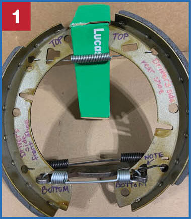
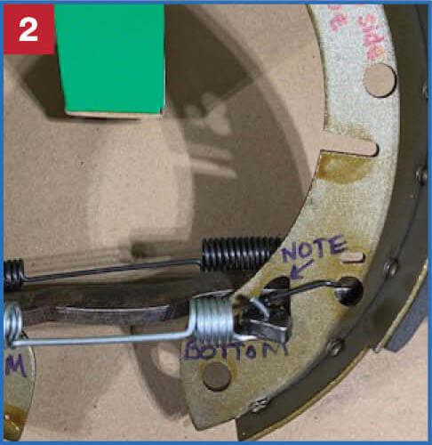
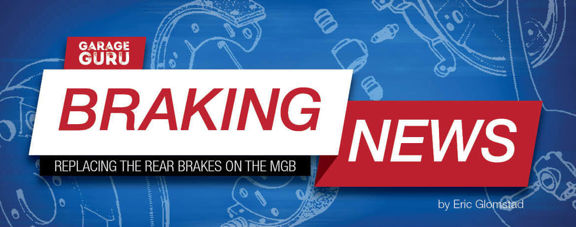
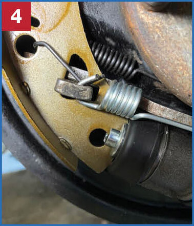
The brake shoes are interchangeable front to back and side to side, so note that the front (leading shoe) has the bare area on the top, while the rear (trailing shoe) has the bare area on the bottom (photo 1). The brake shoe separating springs mount behind the shoes and the ends are captured in the round holes, not the slots. The separating spring on the bottom has the funny angles on the end and this passes through the rear shoe (photo 2). The e-brake levers are situated with the long lever on top and the short lever pointing to the rear of the car. The e-brake spring connects to the lever assembly where it passes through the brake shoes on the front side. This spring attaches from the bottom and up through the holes in the levers (photo 3). Note that the funny angled end of the separating spring sits ON TOP of the e-brake lever (photo 4).
I removed and replaced the cylinders on each side. The bleed screws should be removed for this step. The e-clip that holds the cylinders in place on the backing plate is problematic. Removing the old e-clip prior to pulling the frozen cylinder off the backing plate was accomplished with a flat blade screwdriver. I pried it off and away with a loud “snap” that sent the e-clip on a journey to a remote part of my garage. The new e-clip went on with a lot of effort, two screwdrivers, a welding clamp, and a prayer. I know this is not helpful, except for the prayer, but challenges build character.
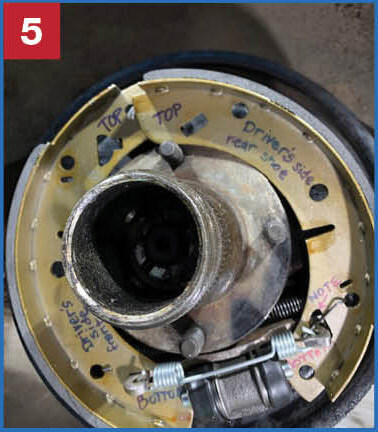
The entire brake shoe assembly is slid onto the backing pate and only the top separating spring is uninstalled (photo 5). Once the bottom of each shoe is in the piston slots of the cylinder, the assembly will stay in place. Then, the remaining spring is installed in the top of each shoe while they are “out front” of the adjusting mechanism. Next, the top of the shoes were stretched apart and snapped into the adjusting mechanism rods.
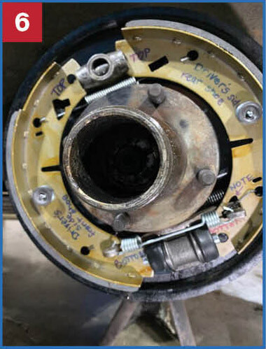
All that remained was to install the shoe locking pins and springs (photo 6). Water pump pliers work well for this last step. With everything connected, the brake assembly should move a little when pushed from side to side. The drum slipped over the assembly easily and without drag. Of course, the next steps are adjustment of the brakes and bleeding the cylinders. These steps are well documented on the internet. MM

'Braking News' has 1 comment
June 10, 2022 @ 6:29 pm Robert Hartmaier
Best article on the proper way to assemble MGB rear brakes that I have seen!